
Environmental Fluid Mechanics Teaching Laboratory
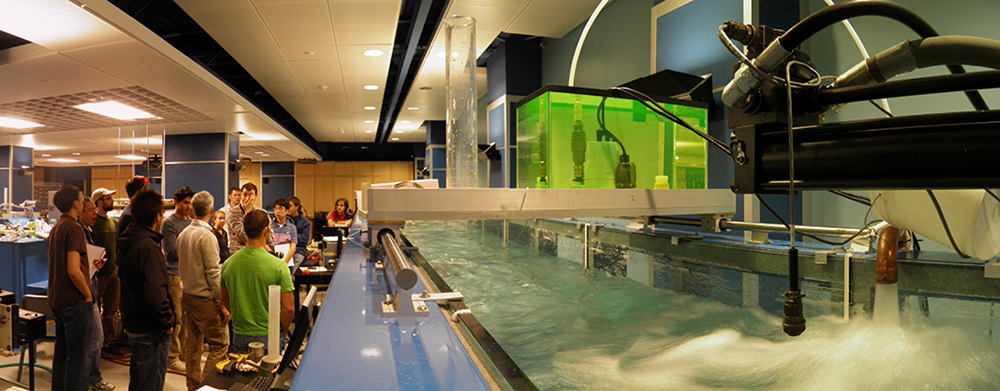
The fundamental concept of this 3,195-sq-ft “open” space is its dual-use nature. Comprised of a Large-Scale Experimental Facility and the Environmental Technology Instructional Lab, it juxtaposes classroom study with research projects and brings together undergrads with graduate students to create a stimulating, learning environment.
On entering this space the eye is drawn to a large flume that runs the length of the lab. This is the wave tank, one of three flumes in the experimental area. Its particular use is for the study of water-waves and their effects on beaches and to study the generation and dissipation of tsunamis. The Facility also includes a high-head flume to examine open-channel hydraulic flows and a sediment flume to test sediment transport typical of rivers, streams, and aqueduct systems.
The second major feature of this space is the Environmental Technology Instructional Lab designed with a flexible instructional area and space for setting up smaller-scale, hands-on fluids projects. The classroom will also be equipped with a computer projection system and internet connection.
This innovative teaching laboratory plays an important role in complementing the studies in the adjacent DeFrees Hydraulics Lab as well as field studies entailing regional streams, rivers, and lakes.
The dual-use nature of this space is aptly demonstrated by the following example from course CEE 331 Fluid Mechanics. Working in teams of three, the students’ labs require much hands-on activity. Through lessons that are largely self-directed and open-ended, the teams are encouraged to “play” with an experiment and thereby develop a deeper, intuitive feeling for fluid mechanics.
Meanwhile these students witness research projects occurring in this same space. The intent of this design was purposeful to bring undergraduates and graduates students closer together - the former get greater exposure to research while the latter naturally assume roles as mentors and teachers. This experience introduces new ideas and roles and may even serve to influence future career decisions.
The facilities described below were designed to our specifications by Engineering Laboratory Design, Inc., and funded through University Facility Renovation Support.
Wave Tank with Material Release Gate
The Wave Tanks with Material Release Gate (WTMRG) is designed to model a complex variety of waves. It is equipped with both a hydraulic wave paddle, located at one end of the facility, and a unique computer controlled material release gate, that can be arbitrarily positioned along the length of the tank. This release gate is designed to simulate landslide generated tsunamis (granular material releases) as well as sudden dam failures (water releases). The facility is constructed entirely of Plexiglas and plate glass and has superb optical access, both for flow visualization and quantitative imaging measurements.
The test section, which is 15m long, .8m wide, and .88m deep, has side walls constructed of plate glass and a bed constructed of SAR abrasion-resistant Plexiglas. The facility is supported by a steel frame, allowing excellent optical access from all sides, including from below. Located approximately at mid-tank is a false-bottom test section that can be utilized for a variety of studies, including sediment transport, fluid-structure, interaction, and flow over irregular morphology.
The hydraulic wave paddle has a maximum stroke of 36 inches and is capable of driving regular and irregular waves across a broad frequency spectrum. The hydraulic material release gate can be positioned essentially anywhere along the test section and is capable of nearly instantaneous removal (for a simulation of dam breaks) as well as following a detailed prescribed removal to simulate material slumps.
Teaching Flume
The Teaching Flume is designed to allow a wide variety of hydraulic flows to be physically modeled. The test section, which is 4.5m long, .6m wide, and .5m deep, has side-walls constructed of plate glass and a bed constructed of SAR abrasion resistant Plexiglas. The facility is supported by a tilting steel frame allowing excellent optical access from all sides, including from below, and bed slopes of -0.5 to +2.0%. The facility is of re-circulating type and is equipped with three 316 stainless steel centrifugal pumps controlled by variable frequency inverters with a maximum combined flow rate capacity in excess of o.1m3/s (1600 GPM). A venturi flow meter and differential pressure sensor are located in the return flow loop to monitor the flow rate in real-time. The upstream end is fitted with a head box with a moveable sluice gate and the downstream end is fitted with a moveable tail gate (sharp crested weir).
The test section is fitted with a nominal 100cm by 30cm standard aperture in its Plexiglas floor together with a flanged insert piece. This aperture and insert match those of the Sediment Flume and the Wave Tank with Material Release Gate and allow standard bed-mounted fittings to be exchanged between the facilities (for example, the sediment test facility described in the Sediment Flume information, below).
The facility has essentially identical cross sectional characteristics as the Sediment Flume (located adjacent and parallel to this facility) allowing clear water and sediment laden water studies to be conducted simultaneously.
Sediment Flume
The Sediment Flume is designed to allow a variety of non-cohesive and cohesive sediment erosion and transport flows to be physically modeled, as well as the general study of open channel hydraulics. The unique aspect of the facility is its sediment chamber with a computer-controlled false bottom that allows vertical repositioning of a sediment bed surface to an accuracy of 10 micron. This capability is used for erosion rate studies.
The test section, which is 8m long, .6m wide, and .6m deep, has side-walls constructed of plate glass and a bed constructed of SAR abrasion resistant Plexiglas. The facility is supported by a tilting steel frame allowing excellent optical access from all sides, including from below, and bed slopes of -0.5 to +2.0%. The facility is of re-circulating type and is equipped with two inert slurry capable centrifugal pumps driven by 25 HP motors and controlled by variable frequency inverters with a maximum combined flow rate capacity in excess of .25m3/s (4000 GPM) allowing flow speeds in excess of 2m/s at flow depths of 20cm. A venturi flow meter and differential pressure sensor are located in the return flow loop to monitor the flow rate in real-time. The upstream end is fitted with a head box with a moveable sluice gate.
The sediment test section is 87.25cm long, 23.60cm wide, and 12cm deep. It is positioned in the vertical with a computer controlled stepper motor that drives parallel (twin) Velmex BiSlides with a vertical positional accuracy of 10 micron. This chamber can be fitted with a square cell with length and width of 23.6 cm.
Emergency Contact
Edwin (Todd) Cowen
Email: eac20@cornell.edu
Phone: (607) 255-5140
Laboratory location: B52 Hollister (basement-level)